User know-how
Basics
Why are tools made of different cutting materials?
Why are there different carbide grades?
Bending strength or wear resistance
For physical reasons, increasing wear resistance of the cutting material results in decreasing bending strength. With increasing hardness, the cutting materials get more brittle. Vice versa, less hard cutting materials have a higher bending strength.
Both are features which have a more or less favourable influence depending on the application.
Which carbide grade is used for which application?
Polycrystalline diamond, one of the hardest and most wear resistant cutting materials, is at the same time one of the most brittle cutting materials. In case of impact the cutting material quickly breaks.
High-speed steel (HS) is one of the softest cutting materials, more resistant to impacts but the cutting edges become blunt quickly. In tests with panel sizing saw blades an edge life of 500 km was reached with a diamond-tipped saw blade, which is equivalent to the distance between Berlin to Frankfurt. Under the same conditions a carbide-tipped saw blade (HW-tipped) reached only an edge life of 2.5 km, which is not even equivalent to the distance straight through Berlin.
The difference in tungsten carbides
Permanent development of the tungsten carbide cutting material allows an increasingly wider range of applications. This is why LEUCO offers HW cutting materials with user-oriented features. Whereas formerly soft wood was machined almost exclusively with HS tools, today the tough HW cutting material „HL Solid 20“is used for spruce, fir, pine, alder etc.. For cuts in particle boards, MDF boards or hard woods we recommend „HL Board 06“. In the case of highly abrasive workpiece materials such as highly compressed or cement-bound particle boards „HL Board 01“ is best for use.
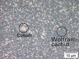
HW is industrially produced in a sensitive process. It consists of cobalt and tungsten carbide (WC). The physical law for cutting materials is also true within the HW cutting material group. A glance through the microscope shows the difference between the HW grades: The higher the tungsten carbide share, the harder, more brittle and more wear resistant is the HW material.
Quality for HW cutting materials
Depending on the manufacturer and the production site, even within a single HW grade there are quality differences not visible to the naked eye, only on the price label. The glance through the microscope shows the difference. Compression failures, lack or excess of carbon lead to increased porosity, slotted pores and a larger WC microstructure. The result is a deterioration of the mechanical features, an increase of the breaking risk and a decrease of hardness.
Summary
The machining quality is determined by several factors, e.g. the choice of the right tool, the cutting geometry etc. The cutting edge material considerably contributes to the optimization of edge life and cutting quality. The “ideal cutting material” would have to have bending strength and wear resistance in equal measure. However, in spite of intensive research this still is wishful thinking.
- What can be done, is to choose the right cutting material according to the respective demands (cutting quality, price-performance-ratio, machine downtimes etc.).
LEUCO not only offers tools but also a wide range of cutting materials for the most different applications.

Placement of cutting materials between two totally opposing demands "wear resistance" and "toughness".

Tungsten carbide grades - variety at LEUCO

Assembling of tungsten carbide - The ratio "Cobalt to "tungsten carbide" and the size of a special grain size varies according to the HW grade.
Technical Information
Important definitions in woodworking
Tool types
One-piece tools (solid tungsten carbide tool / solid steel tool)
Tools without combined or removable parts; the body and the cutting parts are made from one piece.
Composite tools (tipped tools)
Tools with cutting parts (cutting tips) which are tightly connected with the body by means of welding, soft-soldering, hard-soldering, non-detachable bonding, etc.
Complex tools
Tools consisting of a body and one or more cutting parts (exchangeable inserts, knives) which can be changed by means of unlockable clamping elements. The cutting parts can be made in one-piece or compound design.
Tool set
Single tools which are mounted on a tool carrier and meant to work like one tool.
Tool combination
Unit consisting of multiple loose tools which can be combined with each other in diverse order or can be varied axially in different positions.
Types of feed
Types of feed (according to EN 847-1)
Tool bodies are made from such materials that they can withstand the forces and strains to be expected during use. For this purpose steel- and aluminum materials are used. For shank-type tools supplemental materials are available.
Manual feed (MAN)
Manual feed means manually holding and guiding workpieces or machine elements with tools. Manual feed also includes using a removable feed device that is not interlocked with the tool as well as as a manual push-slide.
Mechanical feed (MEC)
Feed mechanism for the workpiece or the tool, integrated in the machine and by means of which the workpiece or machine element with tool is mechanically clamped and guided during operation.
Angles and cutting edge geometries
diameter D [mm]
cutting width B [mm]
hook angle [°]
wedge angle [°]
shear angle [°]
corner angle [°]
Formulas, standard values and further information
Cutting diameter D [mm] = (1000 x 60 x vc) / (n x π)
RPM n [min-1] = vc x 1000 x 60 / (π x D)
Depth of knife marks t [mm] = fz ² / ( 4 x D)
Medium chip thickness hm [mm] = fz x √ (ae/D)
Cutting speed v c [m/s-1] = π x D x n / (1000 x 60)
Feedrate vf [m/min-1] = fz x n x z / 1000
Feedrate per tooth fz [mm] = vf x 1000 / (n x z)
number of teeth = (vf x 1000) / (fz x n)
For safety reasons (noise emission, danger of rebound) the range of cutting speeds for tools with manual feed (MAN) lies between 40 - 70 m/s.
